Creating a composite device type
A composite device is a device profile that includes more than one device type. Each device type can use its own protocol for communication.
With the composite device type, the user can use two devices for a single monitoring point. For example, a circuit breaker and a monitoring device can provide data to this single point. Because Power Operation combines the functionality of the multiple devices, end users only need to consider a single device when analyzing a location in their system.
NOTE: For instructions on setting up and using Cyber Sciences Sequence of Events Recorder (SER), refer to the system technical note (STN) entitled How can I Use Cyber Sciences SERs with Power SCADA Expert?
To create the composite device type:
- From the Create Device Profiles tab, click Add/Edit.
- At the Add/Edit Device Profile screen, choose whether you are creating a new device or creating from an existing device. If you are creating from a device type, select it. Click Next.
- Still on the Add/Edit Device Profile screen, give the composite device type a name. Optionally, add a description (which will become a tool tip display in later screens). Click Next.
- Choose the device types to be in the composite. Click Next.
- Add the tags you need for each device type listed on the left. To add all of the tags for a device type, highlight the device type name and click the right green arrow.
- To override a tag:
- Highlight the tag, then click Override Tag Name.
- From the Select Tag window, choose the tag you want. If necessary, enter a search term, then click Search to display related tags.
- Choose the tag, then click OK.
Only or composite devices, the Is Device Tag check box displays. Use this box to tie a tag back to its actual physical device. For example, you might have the same tag in each of three devices, and you want to set PC-based alarms for each one. Normally, the composite device would generate a single alarm, but you would not be able to specify which physical device has the problem. To prevent confusion, you would check the Is Device Tag, which will cause Power Operation to report this tag for its physical device.
- Check Is Device Tag to read this tag as specific to the physical device, not the entire profile..
- Click Next to begin selecting tags for PC-based alarms and trends.
- For each tag in the profile, determine whether it should have a PC-based alarm or trend associated with it. Check the boxes as appropriate.
- The Driver Parameters box allows you to specify certain parameters to be attached to device profiles. Currently used in IEC 61850 devices, the available parameters will automatically populate this box. See the illustration below for an example.
- Check the parameter(s) that you want to include in this profile.
- To edit, this parameter, return to the Create Device Profiles tab, and click the Parameters sub-tab. See Managing IEC 61850 datasets and Edit IEC 61850 Report control blocks for information on editing these two parameters.
- Check the Close Wizard box, and click Finish to return to Create Device Profiles tab. Or, leave it unchecked, and click Finish to return to the Add/Edit Device Profile screen.
The Add/Edit Device Profile displays with only device type tags available for selection.
The Add/Edit Device Profile displays with only device type tags available for selection.
You may find, especially when dealing with generic I/O, that the tag name is not descriptive enough to determine what it is when reading data in runtime mode. Thus, you may want to override the generic name with something more meaningful.
For example, a device may have ten inputs: Ind1, Ind2, Ind3, etc. Using those names, you have no idea what each input is reading. If you override the tag, the tag's value will still come from the original tag (it still keeps the addressing from the device); however the tag's appearance (name, metadata, display name) will be taken from the new tag.
When the profile is added to the project, PC based alarms are added to the Analog Alarms or Digital Alarms file.
When the profile is added to the project, historical trends are added to the Trend Tags file. Logging will automatically begin when the tag is added to the project.
There are two different intervals for scanning trend tags. All selected tags are scanned every 15 minutes with FIFO storage of 12 months. For the following tags, there is an additional “short” scanning interval of 5-seconds, with FIFO storage of two weeks:
Current A, Current B, Current C, Voltage A-B, Voltage B-C, Voltage C-A, Power Factor Total, Apparent Power Total, Reactive Power Total, Real Power Total, and Frequency.
For instructions on changing the “short” scan interval settings, see Trend tag scan intervals.
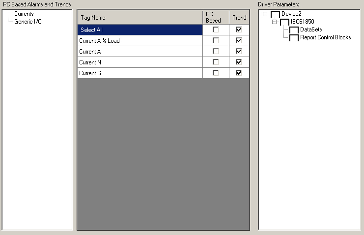
In this example, Device 2 has two parameters, DataSets and Report Control Blocks.